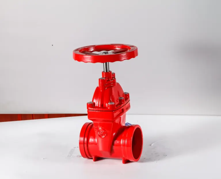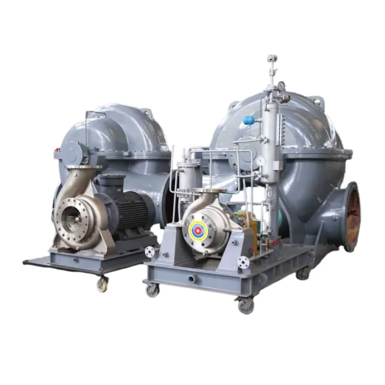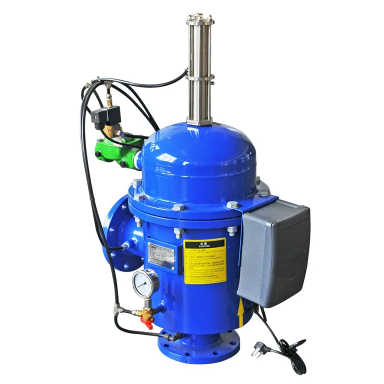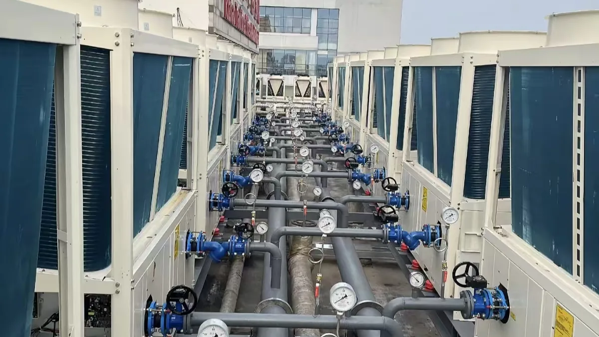
Matching nominal size is only the first step. Equipment of the same size can still have different flange bolt patterns, facings, face-to-face lengths or allowable nozzle loads.
Check along the whole connection chain
Start from each pump nozzle and work through the reducers, valves and instruments in turn. Record the drawing number, connection standard, pressure rating, facing, gasket and fastener requirements. Compare dimensions on approved drawings, not just photos. Also confirm the space needed for actuator operation and for removing strainer baskets and pump parts.
Give each connection one row in an interface register, stating who supplies the mating part and who confirms compatibility. If a drawing is missing, keep the item open; never assume it will fit.
Check loads, not just dimensions
Piping must not use the pump as an anchor point. Even when the bolt holes line up, pipe weight and thermal movement can still apply forces and moments. The piping designer should check supports against the allowable nozzle loads. A flexible joint does not automatically remove this responsibility.
Close all open interfaces before release for manufacturing. With the piping layout and interface list, KFE can coordinate the equipment-side data; site support design and final engineering approval remain with the project’s qualified engineers.
Related industry: HVAC