For: EPC contractors building pump and valve lists from P&IDs (piping and instrumentation diagrams) for RFQs and procurement.
Why the List Has to Be Right
- Missing items: You find the gap during construction, place a rush order and lose time.
- Wrong specs: Pump head too low, valve size or rating wrong, and the equipment can’t be used when it arrives.
- Wrong quantities: Overbuying ties up cash; underbuying means a second purchase.
1. Extracting the List from P&IDs (4 Steps)
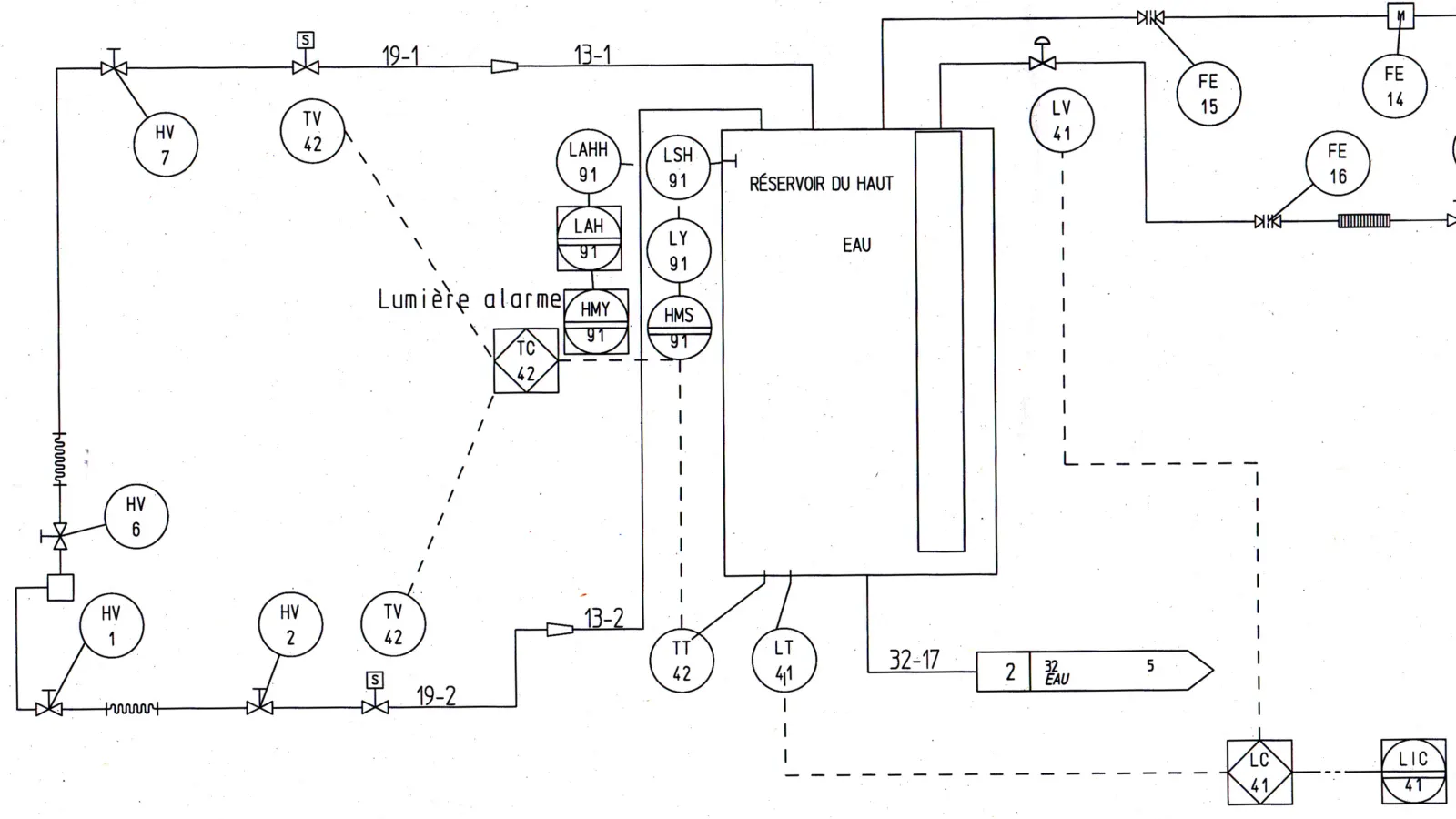
Start with the legend sheet. Symbols and numbering rules vary between projects and design consultants, so the legend sheet always wins.
Step 1: Pumps
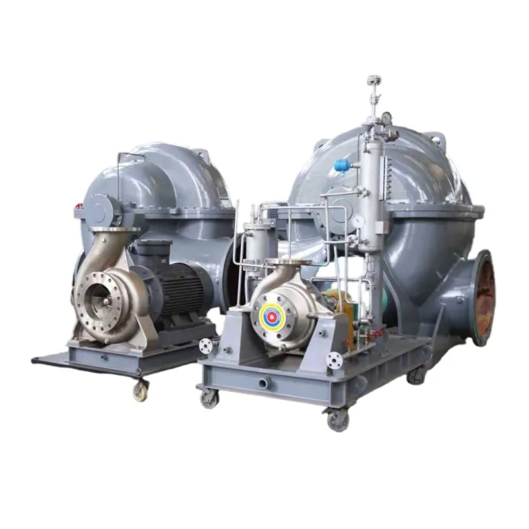
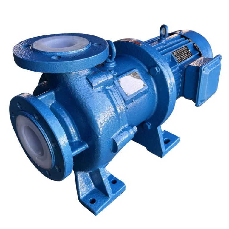
Typical symbols: A centrifugal pump is usually a circle with the discharge nozzle leaving tangentially from the top. Positive displacement and metering pumps vary more, so check the legend.
What to capture:
- Tag: e.g. P-101A/B. A/B means two units, usually duty/standby.
- Flow Q and head H: e.g. 100 m³/h, 50 m. These usually sit in the equipment list or pump datasheet, not always on the P&ID.
- Fluid: clean water, wastewater, seawater, chemicals. Note solids or high viscosity.
- Temperature: ambient, 80°C, 150°C, etc.
- Material: cast iron, 304, 316L, duplex, etc.
- Power supply: voltage and frequency. Saudi Arabia runs at 60 Hz; the UAE, Malaysia and Vietnam run at 50 Hz. The same pump at 60 Hz turns about 20% faster, giving roughly 1.44× the head and 1.73× the power, so the list must state it.
Step 2: Valves
Typical symbols (check the legend):
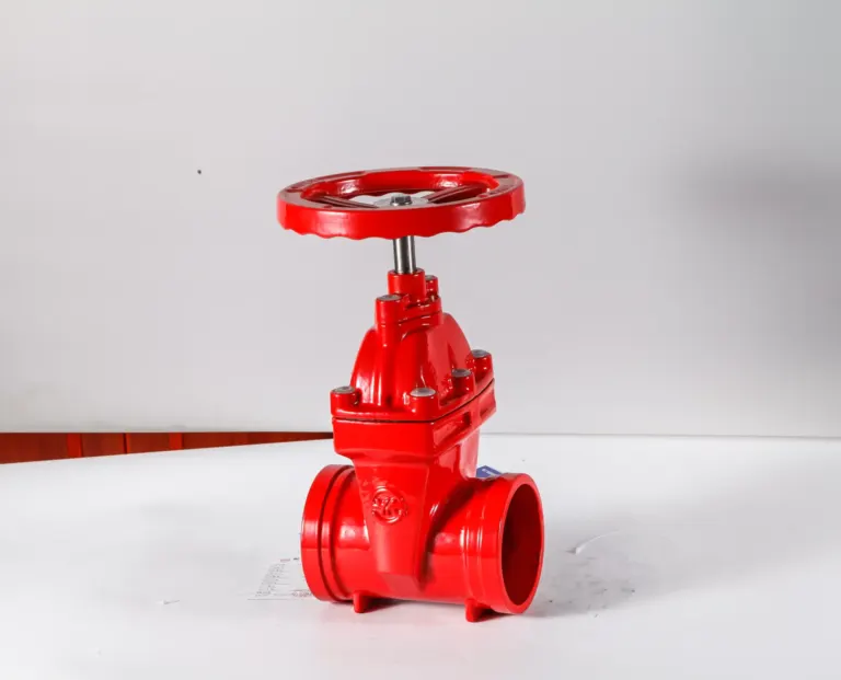
- Gate valve: two triangles tip to tip (bow-tie).
- Globe valve: bow-tie with a solid dot in the middle.
- Ball valve: bow-tie with a circle in the middle.
- Check valve: bow-tie with a flow arrow, or one triangle filled in.
- Control valve: valve body with an actuator drawn on top (e.g. a half-circle diaphragm head).
What to capture:
- Line number: commonly “size-service code-sequence-piping class”, e.g. 200-WS-1001-A1. Follow the project’s numbering rules.
- Valve type and size: gate, butterfly, ball; DN50, DN100, DN200, etc.
- Rating and material: usually not on the P&ID. Take the piping class from the line number and look it up in the Piping Class specification for PN or ASME Class, body material, end connection and flange standard.
Step 3: Count Quantities
- Mark counted pumps and valves on the P&ID with a highlighter to avoid misses and double counts.
- Merge items with the same spec and material into one line.
- A/B tags: P-101A/B = 2 units; P-101A/B/C = 3 units (e.g. two duty, one standby).
- Warehouse spares: spare pumps or valves not installed on the line don’t appear on the P&ID. List them separately.
Step 4: Add Accessories
Pumps: baseplate, coupling and guard usually come with the pump package; state in the RFQ whether they are included. List anchor bolts and seal spares according to the project spares list (commissioning and operating spares).
Valves:
- Mating flanges: count only where the valve connects to welded pipe and needs separate flanges, 2 per flanged valve. First check whether the piping MTO already covers them.
- Gaskets: 1 per flanged joint, so 2 per flanged valve. Rubber-lined wafer butterfly valves usually need no separate gasket.
- Bolts and nuts: look up the flange standard, e.g. EN 1092-1 PN10 DN200 takes 8 × M20. Wafer valves need long studs through both flanges.
2. List Templates (Excel)
Pump List
| No. | Tag | Type | Flow (m³/h) | Head (m) | Motor (kW) | Fluid | Temp (°C) | Material | Power Supply | Qty | Notes |
|---|---|---|---|---|---|---|---|---|---|---|---|
| 1 | P-101A/B | Centrifugal | 100 | 50 | 22 | Clean water | Ambient | Cast iron | 400 V / 50 Hz | 2 | Duty/standby |
| 2 | P-102 | Metering | 0.05 | 50 | 0.37 | HCl 30% | Ambient | PVDF head | 400 V / 50 Hz | 1 | = 50 L/h |
Quick power check: shaft power ≈ ρ × g × Q × H ÷ η. For P-101: 1000 × 9.81 × (100 ÷ 3600) × 50 ÷ 0.75 ≈ 18.2 kW, so a 22 kW motor with margin. The 0.75 efficiency is only an estimate; use the pump maker’s data.
Valve List
| No. | Line No. | Valve Type | Size | Rating | Material | Qty | Mating Flanges | Gaskets | Notes |
|---|---|---|---|---|---|---|---|---|---|
| 1 | 200-WS-1001 | Gate (flanged) | DN200 | PN10 | Ductile iron | 10 | 20 pcs | 20 pcs | 8 × M20 per flange |
| 2 | 100-WS-1002 | Butterfly (wafer, rubber-lined) | DN100 | PN16 | Ductile iron body, 304 disc | 15 | 30 pcs | Not required | Long studs |
3. Common Mistakes
Mistake 1: Counting the Main Line, Missing Branches
The DN200 main line valves are counted, but the valves on ten DN50 branches are not. Fix: check every line, including branches, drains, vents and sample points.
Mistake 2: Missing the Standby Pump
P-101A/B listed as 1 unit. Fix: count units from the tag suffix: A/B is 2, A/B/C is 3.
Mistake 3: Material Doesn’t Suit the Fluid
Cast iron valves on a seawater line corrode quickly. Gulf seawater is warm and highly saline, and even 316 stainless carries a pitting and crevice corrosion risk; duplex, aluminium bronze or rubber-lined ductile iron are common choices. Fix: check corrosion tables against fluid, temperature, velocity and chloride level. For strong acids, select by the specific acid and concentration, e.g. PTFE/PFA-lined.
Mistake 4: Checking Pressure but Not Temperature
Allowable pressure for a given rating drops at higher temperature. Fix: check design pressure and design temperature together against the standard’s pressure-temperature ratings (e.g. EN 1092-1, ASME B16.34).
4. Pre-RFQ Checklist
| Check Item | ✓ / ✗ |
|---|---|
| All pumps: tag, flow, head, fluid, temperature, material filled in | |
| Power supply voltage and frequency stated (50 Hz / 60 Hz) | |
| A/B and A/B/C tags counted by suffix | |
| All valves: size, rating, material, end connection taken from the piping class | |
| Valve quantities match the P&ID; branches, drains and vents checked | |
| Flange, gasket and bolt scope checked against the piping MTO, no double counting | |
| Material compatible with the fluid (corrosion table checked) | |
| Rating confirmed for design pressure and design temperature |
5. Tools
Tool 1: Excel + P&ID PDF
P&ID on one screen, Excel template on the other. Enter page by page, then filter and sort to merge identical items.
Tool 2: CAD Data Extraction
For CAD-format P&IDs, AutoCAD’s built-in EATTEXT (Data Extraction) command exports block attributes (tag, specs) to Excel. Drawings made in intelligent P&ID software such as AutoCAD Plant 3D or SmartPlant P&ID can export equipment and valve reports directly. Always review the export.
Tool 3: OCR
For scanned P&IDs, OCR (e.g. Tesseract) plus custom rules can pull text such as “P-101” and “DN200” into a first draft. Results depend heavily on drawing quality, so every line needs a manual check.
Summary: An Accurate List Means Fewer Revisions in RFQ and Procurement
- Check every P&ID page: main lines, branches and standby units. Read the legend first.
- Use the piping class: valve rating, material and end connection come from the piping class specification.
- Review before the RFQ: material vs fluid, pressure and temperature, power frequency, quantities and scope of supply.
Once your list is ready, send KFE the equipment list (or the P&IDs and piping class) with operating data (flow, head or pressure, fluid, temperature, power supply), and we will work out the selection and quotation.
If you are sourcing pumps, valves or related equipment for a project, send KFE your equipment list and operating data and we will help with selection and quotation.
Related industry: Metals & Power Generation