Piping design involves extensive engineering calculations, material specifications, fabrication requirements and quality standards. Whether for process piping in a chemical plant, oil and gas pipelines or utility networks, engineers must navigate several standard systems while ensuring safety, reliability and compliance. This article reviews the main codes and standards in industrial piping system design.
Overview of Piping Design Codes
ASME B31 Pressure Piping Codes
The ASME B31 series covers almost every industrial piping application:
| Code | Scope |
|---|---|
| ASME B31.1 Power Piping | Steam and hot water systems in power plants, including boiler external piping, turbine connections and auxiliary systems |
| ASME B31.3 Process Piping | Chemical plants, refineries and related processing facilities; the most widely used code for industrial process piping |
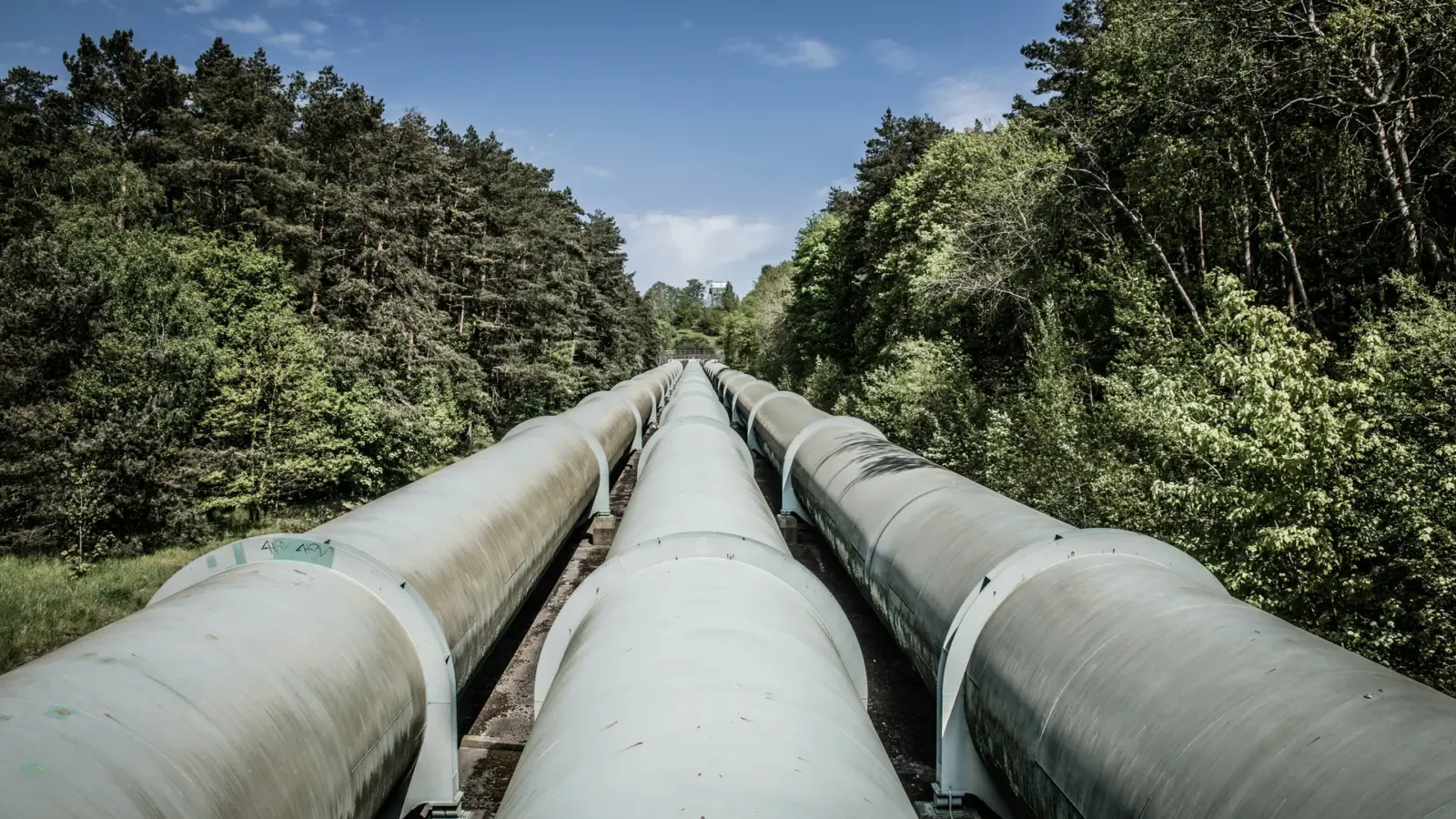
| ASME B31.4 Pipeline Transportation Systems for Liquids and Slurries | Long-distance pipelines for liquid petroleum products and slurries |
| ASME B31.8 Gas Transmission and Distribution Piping Systems | Natural gas transmission, distribution and gathering pipelines |
| ASME B31.9 Building Services Piping | Building utility systems such as HVAC and compressed air |
API Pipeline Standards
API standards add requirements for the oil and gas industry: API 5L specifies seamless and welded steel line pipe for pipeline systems; API 1104 covers welding procedures, qualification and acceptance criteria for pipeline construction; API RP 1110 gives guidance on hydrostatic and pneumatic testing of steel pipelines.
Other International and National Standards
ISO 13623 (petroleum and natural gas industries, pipeline transportation systems) is the international standard harmonising pipeline design practice worldwide; EN 13480 is the European standard for industrial metallic piping; GB 50316 is China’s design code for industrial metallic piping.
Design Pressure and Design Temperature
Setting Design Pressure
Design pressure must be no lower than the maximum expected operating pressure, with a suitable margin. Internal pressure design should start from the maximum operating pressure and consider pressure fluctuations, control valve closure or pump deadheading. Piping under vacuum or external loads needs buckling pressure calculations with appropriate safety factors. Transient pressures caused by valve operation or pump start/stop require surge analysis through water hammer calculations.
Design Temperature Considerations
Design temperature determines material selection and allowable stress. Maximum design temperature is the highest metal temperature expected in operation, including the effects of insulation and solar radiation where needed. Minimum design temperature is the lowest metal temperature during operation, depressurisation or auto-refrigeration, and may require impact testing and special materials. Piping with frequent temperature changes needs fatigue analysis and thermal expansion stress evaluation.
Wall Thickness Calculation
Straight Pipe Wall Thickness
The ASME B31.3 formula for minimum wall thickness of straight pipe is:
t = (P × D) / (2 × S × E × W) + C
Where t is the minimum required wall thickness, P is internal design pressure, D is pipe outside diameter, S is allowable stress at design temperature, E is the weld joint quality factor, W is the weld strength reduction factor and C is the sum of allowances for corrosion, erosion and thread cutting.
Wall Thickness of Piping Components
Elbows and bends need extra wall thickness for pressure loads and flexibility, and bend radius affects the required thickness. Concentric and eccentric reducers must be checked at both the large and small ends for pressure and transition stresses. Branch connections need area replacement reinforcement, finite element analysis or standard fittings to handle complex stresses.
Material Selection Standards
Pipe Materials
- Carbon steel: A106 (seamless), A53 (welded or seamless) and API 5L (line pipe) for general service at moderate temperatures.
- Stainless steel: A312 (seamless or welded) in grades such as 304L, 316L and 321, for corrosive or high-temperature service.
- Alloy steel: A335 chrome-moly steels (P5, P9, P11, P22, P91) for high-temperature service above 400°C.
- Non-ferrous metals: copper, aluminium, nickel alloys and titanium for special corrosion resistance or cryogenic requirements.
Contents of a Material Specification
Each material specification defines: chemical composition limits for carbon, manganese, phosphorus, sulphur and alloying elements; mechanical properties such as minimum tensile strength, yield strength and elongation; manufacturing methods such as seamless, electric resistance welded (ERW) and double submerged arc welded (DSAW); and heat treatment conditions such as normalised, normalised and tempered, quenched and tempered, or solution annealed.
Material Testing Requirements
Mill test reports (MTR) certify that chemical composition and mechanical properties meet the specification. ASME B31.3 requires Charpy V-notch impact testing to confirm material toughness for low-temperature service below −29°C or where the project requires it. Critical services also need non-destructive testing such as radiography or ultrasonics to verify manufacturing quality.
Piping Component Standards
Fittings
ASME B16.9 covers factory-made wrought steel butt welding fittings (elbows, tees, reducers, caps); ASME B16.11 covers forged socket welding and threaded fittings; MSS SP-75 covers high-strength butt welding fittings for demanding services.
Flanges
ASME B16.5 covers pipe flanges and flanged fittings up to NPS 24 in pressure classes 150 to 2500; ASME B16.47 covers large diameter steel flanges from NPS 26 to NPS 60; ASME B16.36 covers orifice flanges for flow measurement.
Valves
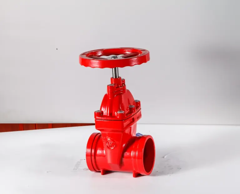
ASME B16.34 sets pressure-temperature ratings and minimum wall thickness for flanged, threaded and welding end valves; API 6D sets specific requirements for pipeline valves used for isolation in transmission pipelines; API 598 covers valve inspection and testing, including shell tests and seat leakage tests.
Flexibility Analysis and Pipe Support Design
Thermal Expansion Analysis
Piping systems must absorb thermal expansion without overstressing pipe, components or connected equipment. Thermal expansion is calculated as:
ΔL = α × L × ΔT
Where ΔL is the expansion, α is the coefficient of linear expansion, L is pipe length and ΔT is the temperature difference from installation to operating temperature.
Simple layouts can be checked by hand using the guided cantilever method; complex 3D piping systems are analysed with dedicated pipe stress analysis software using finite element calculations.
Stress Categories
ASME B31.3 divides stresses into categories with separate allowable limits: primary (sustained) stresses from sustained loads such as internal pressure and weight must not exceed the basic allowable stress S; secondary (displacement) stresses from thermal expansion and end displacements are evaluated for their cyclic nature and shakedown, with higher allowables calculated using the stress range factor f; occasional stresses from short-term loads such as wind, earthquake or relief valve discharge may be allowed up to 1.33S.
Support Design
There are three main types of pipe supports: rigid supports, including anchors, fixed points and stops, to control piping movement; spring supports, including variable springs and constant springs, to provide support while accommodating thermal movement; and guides, which restrain lateral movement while allowing axial movement. Support spacing is set by deflection limits, stress criteria and vibration, and maximum spacing tables are provided in codes and engineering standards.
Welding Requirements
Welding Procedure Specification (WPS)
All production welding requires a qualified WPS covering:
- Base material specification and thickness range
- Filler metal specification
- Welding process and parameters
- Preheat and interpass temperature requirements
- Post-weld heat treatment requirements
Welder Qualification
ASME Section IX sets welder performance qualification requirements; API 1104 is a separate qualification system specific to pipeline welding. Requalification is required when essential variables such as material group, thickness range or welding position change.
Weld Joint Design
Butt welds use full penetration groove welds for permanent pressure-retaining joints, with backing rings allowed in specified services. Fillet welds are used for socket welds and attachments, sized for the loads they carry. Branch connections may use reinforced fabricated tees, integrally reinforced fittings or full encirclement saddles, depending on the branch-to-run size ratio and service severity.
Non-Destructive Testing
Radiographic Testing (RT)
Radiographic testing uses X-rays or gamma rays to image and detect internal weld defects. Examination levels range from 100% of all welds, random spot checks (usually 10% to 20% of welds) and spot examination as required by code, to limited or no radiography. ASME B31.3 sets the required examination level based on service severity and fluid category.
Ultrasonic Testing (UT)
For thick-wall pipe or where radiography is limited, ultrasonic testing has advantages: it provides volumetric examination to find defects throughout the weld; shear wave techniques check the weld fusion line and heat affected zone; and it can measure wall thickness to detect corrosion and erosion thinning.
Other NDT Methods
Magnetic particle testing (MT) detects surface and near-surface defects in ferromagnetic materials; penetrant testing (PT) detects surface-breaking defects in all types of material; visual testing (VT) directly checks external surfaces and weld profiles.
Pressure Testing Requirements
Hydrostatic Testing
Hydrostatic testing remains the standard verification method. ASME B31.3 requires a test pressure of 1.5 times design pressure (or 1.5 times the component rating if lower); test pressure is held for at least 10 minutes while checking for leaks; metal temperature should be at least 17°C above the ductile-brittle transition temperature; and test pressure, duration, temperature and inspection results should all be recorded.
Pneumatic Testing
Where hydrostatic testing is not practical, pneumatic testing with air or inert gas may be used. Compressed gas stores a large amount of energy, so the risk is much higher than with hydrostatic testing and extra safety measures are needed. Test pressure is generally 1.1 to 1.15 times design pressure, lower than for hydrostatic testing. The test area should be barricaded, personnel cleared, pressure raised slowly and leak check procedures strictly followed.
Alternative Test Methods
Some services allow an initial service test, pressure testing with the process fluid at start-up; lower-pressure leak tests such as soap solution or halogen leak detection may be used to verify tightness; and when a system is partly filled with liquid, combined hydrostatic and pneumatic testing can be carried out in sequence.
Piping Documentation Requirements
Design Documents
Design documents usually include: a line list showing size, material, insulation, tracing and special requirements for every line; piping isometrics showing routing, elevations, components and fabrication details; a stress analysis report using calculations and software results to show that primary and secondary stresses meet the code; and detailed material specifications for pipe, fittings, flanges, bolting, gaskets and special items.
Fabrication Documents
Fabrication documents include: WPS for all production welds; welder qualification records; material certificates for all pressure-retaining materials; NDT reports such as radiographic films and ultrasonic scan records; and time-temperature charts for post-weld heat treatment.
Quality Records
Quality records include: an inspection and test plan (ITP) defining hold and witness points for the owner and third parties; pressure test parameter and result records; and as-built drawings reflecting site changes.
How KFE Supports Piping Projects
KFE can help check whether calculations for wall thickness, flexibility and support design meet code requirements, recommend suitable materials for specific services and budgets, help prepare piping material specifications and purchase requisitions, and review designs for constructability from a fabrication and installation point of view.
On documentation, we can help compile calculation reports, material data books (material certificates and test reports) and quality records such as welding records, NDT reports and inspection documents. At every stage from concept to commissioning, we can help answer questions on code applicability.
Conclusion
Piping design codes and standards provide the framework for safe and reliable piping systems. By understanding the applicable codes, material requirements, calculation methods and quality assurance requirements, engineers can design piping systems that are both compliant and fit for operation.
Contact KFE about your next piping project. We will help you complete calculations, specifications and quality documentation to meet the international standards your project uses.
Related industry: Chemical & Pharmaceutical