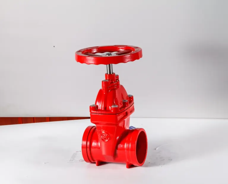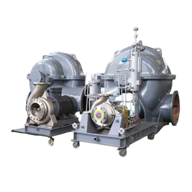
Equipment failures disrupt production and raise costs, and they can challenge even experienced maintenance teams. A systematic troubleshooting approach and a good understanding of common failure modes make it possible to diagnose problems quickly and fix them effectively. This guide covers a structured troubleshooting method, symptom-based diagnosis, and proven solutions for common problems with industrial pumps and valves.
A Systematic Troubleshooting Method
Define the Problem
Start by describing the symptom accurately: what has changed compared with normal operation, when the problem first appeared, under what operating conditions it occurs, and how severe and frequent it is.
Then compare current performance with design specifications, past operating data, similar equipment under the same conditions, and known normal values. Collect objective data at the same time, including flow, pressure, temperature, vibration amplitude and frequency, energy use, and running hours since the last maintenance.
Form Hypotheses
List every cause that could explain the symptom and do not rule anything out too early. Group them into categories:
- Mechanical problems: wear, misalignment, unbalance
- Hydraulic problems: cavitation, recirculation, system changes
- Process changes: fluid properties, temperature, composition
- Instrument errors: sensor faults, calibration drift
- Changes in operating practice
Then rank the possible causes by probability, based on how often they occur in similar cases, the time since the last maintenance, recent changes or modifications, and the known weak points of this type of equipment.
Diagnostic Testing
Begin with non-intrusive checks that do not require disassembly, such as vibration analysis, infrared thermography, performance measurement and visual inspection. If external diagnosis is not enough, move step by step from simple to complex: remove guards and covers for visual inspection, then open the coupling to check alignment, then partly disassemble to inspect suspect parts, and only then carry out a full teardown for internal inspection.
The key is to separate the symptom from the root cause. For example, bearing damage is a symptom whose root cause may be misalignment; seal leakage is a symptom whose root cause may be cavitation or vibration; loss of performance is a symptom whose root cause may be wear or a change in the system.
Common Pump Problems and Solutions
Low Flow or Low Pressure
Symptom: the pump delivers less flow or head than specified. Common causes and solutions are listed below.
Worn or damaged impeller. Inspection may reveal abrasive erosion, chemical corrosion, cavitation damage on the suction side, or mechanical damage from foreign objects. Replace the impeller with a new or repaired part, and find the source of the wear so it can be addressed through better filtration, upgraded materials or adjusted operating conditions.
Wrong direction of rotation. A reversed phase sequence on a three-phase motor makes the pump run backwards and deliver very little flow. Confirm the rotation, then swap any two motor leads to correct it.
Air entrainment at suction. Vortexing at the suction inlet, leaks in the suction pipe, insufficient submergence, or cavitation caused by low NPSH all let air or vapor into the pump and reduce performance. Find the source of the air and solve it by increasing submergence, repairing leaks, fitting an anti-vortex device or increasing the NPSH margin.
System changes. Valves that are not fully open, fouled heat exchangers or strainers, extra pipe length or fittings, and higher fluid viscosity or density all raise system resistance beyond what the pump can deliver. Check the system curve; if the change is permanent, consider trimming the impeller, increasing speed or replacing the pump.
Excessive wear ring clearance. Too much clearance causes internal recirculation and reduces delivered flow. Measure the clearance and replace the wear rings when it exceeds the manufacturer’s limit (typically 2–3 times the new clearance).
Excessive Vibration
Symptom: vibration exceeds acceptance criteria, causing noise, higher bearing loads and seal leakage.
Misalignment. Shaft misalignment between pump and driver: parallel misalignment mainly produces radial vibration at 1x running speed, while angular misalignment mainly produces axial vibration at 1x and 2x running speed. Use a laser alignment tool or dial indicators to align precisely to the manufacturer’s requirements (typically 0.05 mm TIR).
Unbalance. Uneven impeller wear, coupling deterioration, impeller fouling or missing balance weights create rotor mass unbalance and vibration at 1x running speed. Dynamically balance the rotor, remove fouling, or replace the worn parts causing the unbalance.
Cavitation. The formation and collapse of vapor bubbles produces broadband vibration and a characteristic noise like gravel hitting the casing. Raise NPSHa by increasing suction pressure, lowering the pump installation level, reducing suction line losses or lowering fluid temperature; or lower NPSHr by reducing speed or using a different hydraulic design.
Bearing wear. Damaged or degraded bearings show specific defect frequencies, including outer race, inner race, rolling element and cage frequencies. Replace the bearings and identify the root cause, such as lubrication failure, contamination, misalignment or overload.
Pipe strain. External forces from the piping cause misalignment during operation, transmit pipe vibration and restrict thermal expansion. Adjust pipe supports, add expansion loops or reset supports to remove loads from the pump nozzles.
Operating away from BEP. When the operating point is far from the best efficiency point (BEP), flow below 70% of BEP causes low-flow recirculation and flow above 120% of BEP causes high-flow turbulence. Bring the operating point closer to BEP by adjusting system resistance, trimming the impeller, changing speed or replacing the pump with a suitable one.
High Power Consumption
Symptom: motor current or power exceeds the specified value.
Higher flow than expected. System resistance lower than design, several systems running in parallel, or a control valve opened wider than expected makes the pump run beyond its rated point. Increase system resistance (throttling or impeller trimming); if this is a long-term duty, fit a larger motor.
Higher fluid density or viscosity. Higher viscosity at lower temperature, a change in fluid composition or a higher solids content all raise the power demand. For a long-term duty, replace the motor; for a temporary duty, reduce flow or run intermittently to prevent motor overheating.
Mechanical friction. Drag from damaged bearings, seal friction or dry running, internal rubbing from misalignment or poor assembly, and coupling misalignment all increase power consumption. Disassemble and inspect to find the source of friction, correct the alignment and replace worn parts.
Wrong impeller diameter. An oversized impeller pushes flow and power above specification. Verify the impeller diameter and trim it to the correct size if it is too large.
Seal Leakage
Symptom: visible leakage at the mechanical seal or packing.
Normal wear. Seal faces wear over time and eventually leak. Replace the mechanical seal or packing; under normal conditions seal life is generally 1–3 years.
Dry running. Failure of the flush system, low suction pressure, air entrainment or cavitation causes loss of lubrication and rapid seal face wear. Restore proper flushing, ensure adequate suction pressure, eliminate air entrainment and replace the damaged seal.
Excessive vibration. Mechanical vibration from misalignment, unbalance, cavitation or bearing wear can open the seal faces. Eliminate the source of vibration first, then replace the seal if it is damaged.
Chemical attack. Seal materials that are not compatible with the fluid lead to elastomer swelling or degradation, corrosion of metal parts and chemical attack on the seal faces. Switch to chemically compatible materials, using a chemical compatibility chart or the manufacturer’s advice.
Incorrect installation. Wrong seal face setting, faces damaged during installation, dirt between the faces or seal parts fitted the wrong way round all cause immediate or premature failure. Follow the manufacturer’s installation procedure strictly and install the new seal carefully.
Common Valve Problems and Solutions
Valve Does Not Shut Off Tightly
Symptom: fluid still passes after the valve is closed.
Seat damage. Debris trapped between disc and seat, erosion by high-velocity flow or corrosion from stagnant fluid scratches, erodes or corrodes the sealing surfaces. Lap metal seats for minor damage and replace the seat for severe damage; for erosive or corrosive service, improve filtration or change materials.
Damaged disc or plug. Mechanical damage, erosion or cavitation damage, and distortion from thermal cycling all cause the closure member to fail. Replace the disc or plug, and if the damage comes from operating conditions, remove the root cause.
Insufficient actuator thrust. This is especially common in high differential pressure service. Causes include an undersized actuator, low air supply pressure (pneumatic) or worn actuator parts. Raise the air supply pressure within allowable limits, fit a correctly sized actuator or repair the worn actuator.
Valve sticking. A stem binding in the packing or bushing, internal interference from debris or corrosion, and differential thermal expansion all stop the valve from closing fully. Disassemble, clean and remove the interference; if sticking is caused by thermal effects, adjust the packing or bushing clearance.
Excessive Noise
Symptom: the valve is very noisy in operation.
Cavitation. In liquid service, an excessive pressure drop across the valve, downstream pressure close to the fluid’s vapor pressure and insufficient downstream pressure recovery cause bubble collapse. Raise the downstream pressure, use several valves in series to reduce pressure in stages, or select anti-cavitation trim.
Flashing. When downstream pressure is below vapor pressure, the liquid vaporizes and does not condense again. Relocate the valve, raise the downstream pressure, or accept some noise and potential damage.
Choked flow. Gas or steam velocity reaches sonic speed when the pressure ratio across the valve is too high or the valve is too small. Size the valve for an acceptable velocity, install a downstream silencer, or use multi-stage pressure-reducing trim to cut noise.
Mechanical vibration. Loose parts, poor guiding of the disc or plug and high-velocity turbulence make valve components vibrate. Tighten loose parts, replace worn guide bushings, or choose a larger valve to lower velocity.
Control Valve Hunting
Symptom: the valve position swings back and forth, causing process variables to fluctuate.
Poor loop tuning. Too much proportional gain, too short an integral time or too long a derivative time makes the control loop unstable. Retune systematically, for example with the Ziegler-Nichols method, the Cohen-Coon method or dedicated tuning software.
Oversized valve. An oversized valve has too much gain at the operating point, so a small movement causes a large change in flow, and it often works close to the closed position. Reduce the trim size or replace it with a correctly sized valve.
Stick-slip friction. Overtightened packing, poor lubrication, a scored stem or corrosion cause intermittent friction. Adjust the packing, lubricate the stem, or replace the packing and polish the stem.
Sensor problems. Electrical noise in the signal, an unrepresentative measuring point or mismatched response times can also cause hunting. Filter the noisy signal, relocate the sensor or upgrade it.
Diagnostic Tools and Techniques
Vibration Analysis
Handheld data collectors suit route-based data collection: they measure overall vibration (velocity RMS), perform spectrum analysis and compare readings with baselines. For critical equipment, online monitoring systems provide real-time alarms, historical trends and advanced analysis such as shaft orbits, waterfall plots and envelope analysis.
Common frequency signatures and the problems they point to:
| Frequency signature | Possible causes |
|---|---|
| 1x running speed | Unbalance, misalignment, bent shaft |
| 2x running speed | Misalignment, looseness |
| Bearing defect frequencies | Bearing wear |
| Vane pass frequency | Impeller-related problems |
| Subsynchronous frequencies | Recirculation, oil whirl |
Infrared Thermography and Temperature Monitoring
Infrared cameras detect overheated bearings, motor hot spots, process temperature deviations and faulty electrical connections. Bearing and process temperatures can also be logged continuously with RTD or thermocouple arrays, with high-temperature alarm setpoints.
Performance Testing
Use portable ultrasonic or insertion flow meters to verify actual flow, precision pressure gauges to measure suction and discharge pressure, and electrical power meters to measure actual power consumption. Compare measured performance with the baseline and calculate the percentage of performance loss.
Conclusion
Effective troubleshooting takes a systematic method, knowledge of the equipment and the right diagnostic tools. Understanding common failure modes and their root causes helps you solve problems quickly, reduce downtime and prevent recurrence.
If you are sourcing pumps, valves or related equipment for a project, send KFE your equipment list and operating data and we will help with selection and quotation.
Related industry: Metals & Power Generation