For: Design engineers and consultants designing pump stations (pump rooms) for water treatment plants, desalination, chemical plants, power stations, etc.
Why Pump Station Design Matters
Common consequences of poor design:
- Poor intake conditions: Vortexes, air entrainment, uneven flow in suction basin cause pump cavitation, vibration, impeller rapidly damaged.
- Insufficient space: Pumps too close together, cannot extract rotor or motor during maintenance, only by dismantling pipes or breaking walls.
- High pipe stress: Pipe weight and thermal expansion transmitted to pump ports, causing misalignment, bearing damage, flange leakage.
- Water hammer: Sudden pump shutdown or rapid valve closure, pipe pressure violently fluctuates, damaging pipes, valves and supports.
- Inconvenient operation: Valves, instruments installed in unreachable or invisible locations.
Article objective: Provide core points and common errors in pump station design. Values in text are common reference values; final design per project specifications, standards and pump manufacturer data.
I. Intake Basin & Suction Conditions (Reference ANSI/HI 9.8)
1. Submergence Depth & Anti-Vortex
Pumps drawing from open basins or suction wells must have adequate submergence depth at minimum operating water level, otherwise surface vortexes and air intake occur.
- ANSI/HI 9.8 recommended minimum submergence: S = D × (1 + 2.3 Fr), where D = inlet bell diameter, Fr = V / √(gD), V = bell velocity.
- Bell velocity: HI 9.8 provides recommended range, common design value about 1.7 m/s, larger flow needs better control.
- Submergence verified at minimum operating water level, not normal level.
2. Suction Basin Geometry
- Bell to basin floor about 0.3D–0.5D, to back wall not too far (HI 9.8 provides upper limit).
- Multiple pumps side-by-side, inlet must be uniform, avoid one pump downstream of another.
- Approach channel velocity should be low (HI 9.8 suggests about 0.5 m/s or lower), avoid lateral inflow, sudden expansion and dead zones.
- Add guide walls, anti-vortex baffles, floor splitters as needed.
- Large flow or non-standard layout: HI 9.8 suggests hydraulic model testing to confirm no vortexes and prerotation.
3. NPSH Verification
- NPSHa (Available NPSH) must be greater than NPSHr (Required NPSH, usually NPSH at 3% head drop), with adequate margin.
- Margin per ANSI/HI 9.6.1, based on application and suction specific speed, cannot design just at NPSHa = NPSHr.
- NPSHa calculated at worst-case conditions: minimum level, maximum liquid temperature, maximum flow (including flow deviation during single pump operation), strainer blockage resistance.
- Seawater, hot water, volatile media use actual temperature saturation vapor pressure for calculation.
II. Pump Configuration & Layout
1. Operating & Standby Pumps
- Common practice: N operating + 1 standby (N+1), critical water supply, fire or process-critical pump stations per code or owner requirement set N+2 or other standby method.
- Standby pump same model as duty pumps, convenient for interchange and unified spares; control system periodically rotates lead/standby pumps, avoiding long-term non-rotation of standby.
- Parallel operation: During pump selection verify single pump, multi-pump parallel operating points, ensure each pump within allowable operating region; pump curve preferably stable rising to shutoff type.
- Power supply, control cabinets, discharge header also consider redundancy, otherwise standby pump also cannot function.
2. Pump Spacing
Common reference clearances:
- Between pumps: About 1.0–1.5 m (small pumps can reduce appropriately, large pumps need more).
- Pump to wall: About 0.7–1.0 m, convenient for inspection and maintenance.
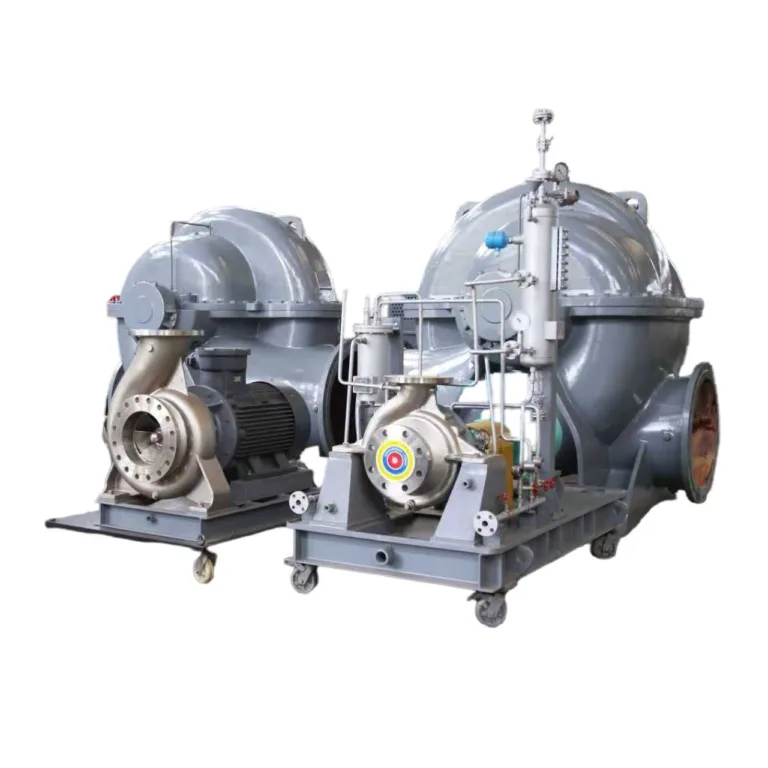
- Maintenance space: Reserve space per pump type for rotor, bearing housing or motor removal. E.g. back pull-out end suction pumps need length for complete rotor assembly extraction; split case pumps need lifting height for pump cover.
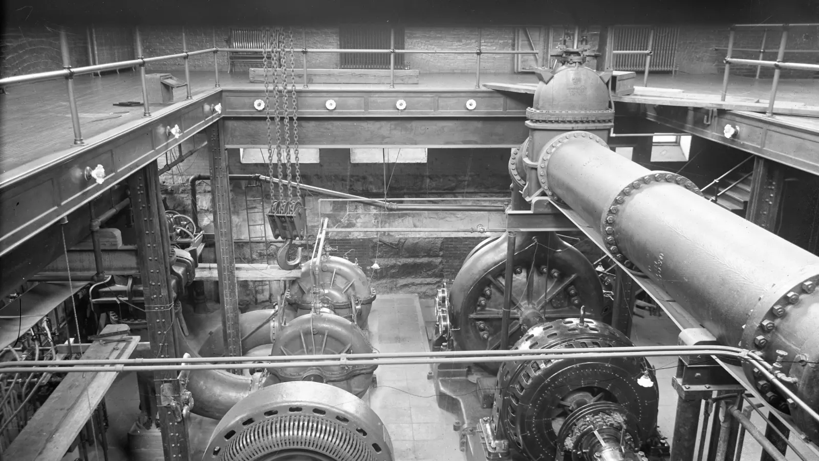
- Lifting equipment: Select crane or hoist per heaviest maintenance part, reserve lifting height and transport passage.
Layout methods:
- Single-row layout: Suitable for fewer pump stations, pumps along one wall.
- Double-row layout: Suitable for medium-large pump stations, main maintenance aisle between two rows (generally around 2 m).
- Group layout: Large pump stations grouped by system, maintenance aisles around.
Vertical vs Horizontal Pumps:
- Vertical pumps: Small footprint, suitable for underground pump rooms, wet pits or tight spaces. Drawback is maintenance requires complete lifting, needs large lifting height; some vertical pumps’ axial thrust borne by motor thrust bearing, motor must match pump selection.
- Horizontal pumps: Large footprint, but convenient maintenance, suitable for surface pump rooms.
III. Pump Foundation & Installation
1. Concrete Foundation
- Foundation height: Generally 100–300 mm above floor, prevent floor water immersion of baseplate.
- Foundation size: Extend about 100–150 mm beyond pump baseplate each side.
- Foundation mass: Common experience not less than 3–5 times pump and motor total weight, final per structural calculation.
- Anchor bolts: Pre-embed per pump manufacturer foundation drawing, or reserve bolt holes for secondary grouting.
- Grouting: After baseplate leveling use non-shrink grout or epoxy grout, ensure baseplate fully contacts foundation.
- Strength: Concrete reaches design strength before grouting and installation (specific curing time per structural engineer requirement).
- After installation and after piping, recheck alignment.
2. Vibration Reduction Measures
Why vibration reduction needed? Pump vibration transmits through foundation to building structure, may cause resonance, amplify noise. High power, high speed pumps more obvious.
Vibration reduction methods:
- Rubber vibration pads: Suitable for small-medium pumps.
- Spring vibration isolators: Better isolation effect, suitable for vibration-sensitive buildings (hospitals, laboratories, high-rise equipment floors).
- Inertia foundation: Set thick heavy concrete block under baseplate, increase mass, reduce vibration transmission, suitable for large pumps.
- With vibration isolation installation, suction and discharge piping must have flexible connections, otherwise vibration isolation ineffective.
IV. Piping Layout
1. Suction Piping
Principles: Short, straight, low velocity, no air pockets, uniform flow to pump.
Key requirements:
- Pipe diameter: Suction pipe usually one to two sizes larger than pump suction port, velocity controlled at low level (common about 1–2 m/s, per NPSH calculation).
- Eccentric reducer: At diameter change use eccentric reducer, flat side up, prevent top air accumulation.
- Slope: Pipe cannot have local high points. Suction lift condition (pump above liquid), pipe continuously rises toward pump; flooded condition (liquid above pump), pipe rises toward basin, letting gas return to basin.
- Suction valve: Flooded condition and common suction header, suction side must set isolation valve (gate or butterfly), fully open during operation, close for maintenance; control must prevent starting pump with valve closed. Suction lift non-self-priming pumps need foot valve or vacuum priming device, self-priming pumps don’t need foot valve.
- Elbows: Minimize. Each elbow local loss = K × v²/2g, related to velocity, not fixed value.
- Straight pipe before pump: Generally leave ≥ 5D straight pipe before pump suction (D = pipe diameter). For double-suction pumps if elbow plane parallel to pump shaft, inflow biases one-side impeller, needs longer straight pipe or change elbow direction, specifics per ANSI/HI 9.6.6.
- Strainer: Temporary strainer (commissioning use) and permanent strainer resistance must be included in NPSHa.
Common errors:
- Suction pipe has “hump” or concentric reducer → air accumulation, pump flow drops, cavitation or even no water. → Use eccentric reducer flat side up, eliminate high points.
- Intake port from tank side has insufficient submergence → forms vortex, sucks air, should increase submergence or add anti-vortex baffle.
2. Discharge Piping
Key requirements:
- Pipe diameter: Discharge pipe usually larger than pump discharge, use concentric reducer to expand.
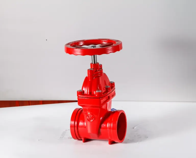
- Sequence: Pump discharge → flexible joint → check valve → isolation valve (gate or butterfly). Check valve close to pump, isolation valve after, so when maintaining check valve can close isolation valve, no need to drain discharge header.
- Check valve selection: Long-distance water transmission or multi-pump parallel, preferably fast-closing no-slam type, such as spring-assisted dual-plate check valve, axial-flow (nozzle) check valve, or check valve with slow-closing device. Ordinary swing check valve prone to disc slamming during pump shutdown.
- Starting method: Radial-flow centrifugal pumps usually start with valve closed (shutoff power lowest), slowly open valve after starting, closed-valve operation time cannot be too long. Mixed-flow pumps, axial-flow pumps have high shutoff power, generally must start with valve open, per pump manufacturer requirements.
- Minimum flow: Pumps running long-term at low flow conditions, set minimum flow recirculation piping.
3. Pipe Supports
- Suction and discharge pipes must have independent supports, pipe weight cannot press on pump.
- Pump port forces and moments cannot exceed pump manufacturer allowable values (API 610 pumps per API 610 nozzle load table, other pumps per manufacturer data).
- Support spacing per pipe diameter, wall thickness and medium weight calculation; high-temperature piping requires stress analysis, properly set fixed supports and sliding supports.
4. Flexible Connections
Why needed? Pipe vibration, thermal expansion and foundation settlement transmitted to pump cause flange leakage, pump casing deformation, misalignment.
Common types:
- Rubber expansion joints: Absorb vibration and minor displacement, suitable for medium-low pressure, normal to medium temperature systems, pressure and temperature per product rating.
- Metal bellows expansion joints: Suitable for higher temperature, pressure systems, used to absorb thermal displacement.
- Dismantling joints (tie-rod joints): Facilitate valve and pump disassembly, some types can transmit axial force.
Note: Expansion joints without tie rods produce pressure thrust (approximately pressure × effective area), this force acts directly on pump ports. Must have limit tie rods, or set fixed supports on piping to bear thrust.
V. Water Hammer Protection
Water hammer sources: Power failure trip, check valve slam closure, rapid valve closure, causing sudden change in pipe flow velocity, inducing pressure fluctuation. Pressure rise can be estimated by Joukowsky formula: Δp ≈ ρ × a × Δv. E.g. steel pipe wave speed a about 1000 m/s, velocity suddenly changes 1 m/s, pressure rises about 1 MPa (10 bar). After pump shutdown can also have negative pressure and water column separation, harm equally great.
Design requirements:
- Long-distance water transmission pipes, high-head pipes, pipelines with large terrain undulation, must do hydraulic transient (water hammer) analysis.
- Select protection measures based on analysis results:; Surge tanks (air chambers, air vessels): Supplement water during pump shutdown, limit pressure drop and rebound.; Air release/vacuum valves: Install at pipe high points, exhaust air, admit air during negative pressure, prevent water column separation.; Slow-closing check valves or non-slam check valves.; Motorized valves close slowly in stages, closing time per analysis results.; Flywheel (some cases) increases rotational inertia, delays flow velocity drop after pump shutdown.
- VFD soft-stop only effective for normal shutdown, no effect during power failure trip, cannot replace water hammer protection facilities.
VI. Instruments & Control
1. Pressure Gauges
- Suction side: Install at pump suction flange vicinity, suction lift use vacuum-pressure gauge (e.g. -0.1–0.6 MPa).
- Discharge side: Install between pump discharge flange and check valve.
- Range: Normal working pressure preferably at 1/3–2/3 of range (approximately 1.5–2 times maximum working pressure).
- Installation: Install instrument valve before gauge, convenient for gauge removal; pulsating cases add snubber (buffer).
2. Flow Meters
- Generally install on straight pipe after discharge check valve and isolation valve.
- Straight pipe: Per flow meter manufacturer requirements. Common requirements: electromagnetic flowmeter 5D upstream, 2–3D downstream; ultrasonic flowmeter and turbine flowmeter usually need longer, e.g. 10D upstream, 5D downstream.
- Electromagnetic flowmeter: Suitable for conductive liquids (water, wastewater, seawater), essentially no pressure loss.
- Turbine flowmeter: Suitable for clean low-viscosity liquids, not for particle-containing media.
- Ultrasonic flowmeter: Clamp-on installation convenient, economical for large diameter, accuracy greatly affected by installation conditions.
3. Automatic Control
Basic control logic:
- Manual/auto switching: Field manual start/stop, auto mode starts/stops per level or pressure.
- Level control: Suction basin low level stops pump (prevent air suction and dry run); discharge basin high level stops pump (prevent overflow).
- Pressure control: Discharge pressure excessive alarm or stop pump; insufficient supply pressure starts next pump or standby pump.
- Motor protection: Overload, phase loss, winding temperature, bearing temperature protection.
- Dry run and low flow protection: Use flow, pressure or motor power signal judgment, delay per pump and mechanical seal manufacturer requirement setting.
- Lead-standby rotation and automatic fault switching.
VFD control:
- Variable frequency drive adjusts speed per flow or pressure, reduces valve throttling loss, and achieves soft start.
- Must verify minimum speed still within pump allowable operating region, motor cooling and bearing currents (large motors) also consider.
VII. Pump Room Environment & Safety
1. Ventilation & Heat Dissipation
Why important? Motor and pump heat causes pump room temperature rise, causing motor insulation aging, bearing temperature rise, personnel cannot inspect long. Gulf region summer high temperatures especially need attention.
- Air volume per heat dissipation: Based on motor losses, VFD heat and outdoor design temperature determine ventilation volume or HVAC load.
- Common reference: Mechanical ventilation air changes not less than 6 per hour, but high-temperature regions and high-power pump rooms often need more, or need AC.
- Inlet and exhaust must be sand-proof, rainproof.
2. Drainage & Waterproofing
- Floor drainage: Floor slopes toward drain (about 1%), collect leakage and maintenance drainage.
- Sump pit: Underground or semi-underground pump rooms set sump pit, with submersible sewage pump auto-drain.
- Waterproofing: Underground pump room walls and floor do waterproofing, and consider flood prevention measures (e.g. motor position above possible flooding level).
3. Lighting & Noise
- Lighting: Illuminance per local code, maintenance areas higher than general areas.
- Noise: 85 dB(A) is many countries’ occupational noise 8-hour exposure control value, when exceeded must take noise reduction measures or wear earplugs; property boundary noise per local environmental requirements, usually stricter.
- Noise reduction measures: Select low-noise motors, set vibration-isolation foundations, wall sound absorption, add silencers to inlet/exhaust.
4. Fire & Safety
- Pump rooms handling flammable liquids (diesel, solvents), per hazardous area classification select explosion-proof motors and instruments (e.g. ATEX, IECEx certification), and per fire code set fire alarm and extinguishing facilities.
- Couplings, belt pulleys and other rotating parts must have guards.
- Hang equipment ID tags on pumps, set safety signs at pump room entrance.
Summary: Good Pump Station Design = Good Intake + Easy Maintenance + Pipes Don’t Load Pump + Water Hammer Protection
4 Principles:
- Get intake conditions right first: Submergence depth, intake flow pattern and NPSH margin determine whether pump can run stable long-term.
- Leave adequate space: Better pump room slightly larger, maintenance can dismantle, can lift.
- Independent pipe support: Pipe weight, thrust and thermal displacement cannot transmit to pump.
- Long pipes must consider water hammer: Power failure trip is most common hazardous condition.
If you are sourcing pumps, valves or related equipment for a project, send KFE your equipment list and operating data and we will help with selection and quotation.
Related industry: HVAC