For: EPC contractors confirming interface compatibility between pumps, valves, piping, instrumentation, and electrical systems before mobilization to avoid on-site mismatches.
Why Check Interfaces in Advance?
Common problems:
- Pump flange is PN16, but mating valve is Class 150 (pressure ratings not exactly equivalent, bolt hole patterns differ).
- Motor is 380V/50Hz, but site power is 440V/60Hz.
- Skid-mounted control panel outputs 4-20mA signal, but DCS requires 0-10V.
- Pump inlet/outlet orientation doesn’t match pipe design, requiring on-site elbows.
Consequences:
- Discovered only after equipment arrival, requiring either factory rework (4–8 week delay) or on-site adapters (increased cost and leakage risk).
- Owner considers this EPC design or procurement error, withholds retention or levies penalties.
I. Mechanical Interfaces
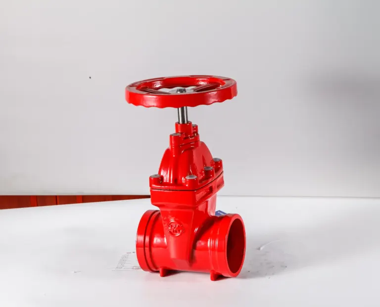
1. Flange Standard and Dimensions
Question: Do pump/valve flanges match pipe flanges?
Check items:
- Standard system: ASME B16.5 (American), EN 1092 (European), GB/T 9119 (Chinese), JIS (Japanese)?; ⚠️ Same pressure class, different standards may have different bolt hole patterns and bolt counts.
- Pressure rating: PN10/16/25/40 (European) vs Class 150/300/600 (American)?; Reference: PN16 ≈ Class 150, but bolt patterns slightly differ; PN25 ≈ Class 300.
- Face type: RF (raised face), FF (flat face), RTJ (ring-type joint)?; When two RF flanges mate, gasket must be non-asbestos or spiral-wound, cannot use rubber flat gasket.
Recommendation:
- In purchase contract, clearly specify: “Flange DN100 PN16 EN 1092-1 Type 01 RF” (size + pressure + standard + type + face).
- If project has mixed European and American standard equipment, prepare adaptor flanges in advance.
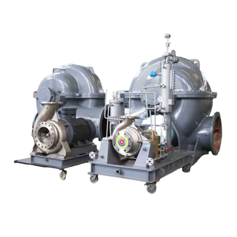
2. Pump Inlet/Outlet Orientation and Pipe Layout
Question: Do pump suction and discharge orientations match pipe design?
Common mismatches:
- Design shows horizontal suction, vertical discharge, but supplier provides vertical suction, horizontal discharge.
- Pump discharge on left side, but site piping on right side.
Check items:
- Require supplier to provide GA Drawing showing inlet/outlet orientation and flange centerline heights.
- Cross-check with piping P&ID and 3D model for clearance.
Interim measures:
- If mismatch, add elbows or spool pieces on site, but note:; Avoid excessive elbows on suction side (increases resistance, affects NPSH).; Elbows must match pump discharge flange pressure rating and material.
3. Pump-Motor Coupling Alignment
Question: Are pump shaft and motor shaft on same centerline?
Check items:
- Does purchase contract specify “pump and motor rough-aligned at factory before shipment”?
- Is alignment data provided (radial offset < 0.05mm, axial offset < 0.05mm)?
Recommendation:
- Large pumps (power > 50kW) require precision alignment at factory with laser alignment report provided.
- Re-alignment required after site installation (foundation settlement, pipe stress cause deviation).
II. Electrical Interfaces
4. Motor Voltage and Frequency
Question: Do motor voltage, frequency, phases match site power supply?
Common mismatches:
- Chinese standard motor (380V/3/50Hz) exported to Middle East (440V/3/60Hz) or North America (460V/3/60Hz).
- Saudi project site is 415V/3/60Hz, but supplier defaults to 380V/50Hz.
Check items:
- In RFQ clearly specify: “Motor 440V/3/60Hz, IE3, IP55.”
- Verify motor nameplate matches contract.
Consequences:
- Voltage mismatch: Motor won’t start or overload burns out.
- Frequency mismatch: 50Hz motor on 60Hz supply, speed increases 20%, flow and head also change (may exceed pump design range).
5. Motor Protection and Explosion-Proof Rating
Question: Do motor protection and explosion-proof ratings meet site environment?
Check items:
- Protection (IP):; Indoor dry environment: IP55 (dust-protected, water jet protected); Outdoor or high humidity: IP65 (dust-tight, water jet protected); Underwater or fully submerged: IP68
- Explosion-proof (Ex):; Flammable/explosive environment (oil depot, chemical plant): Ex d IIB T4 (flameproof) or Ex e (increased safety); Non-hazardous area: Standard motor (20–30% lower cost)
Recommendation:
- Determine explosion-proof requirements based on project area classification (ATEX zoning or IECEx). Don’t blindly choose explosion-proof motors (expensive and long lead time).
6. Control Signals and DCS/PLC Interface
Question: Do VFD and control panel output signals match DCS/PLC?
Common mismatches:
- Pump control panel outputs 4-20mA analog signal, but DCS requires 0-10V.
- Control panel outputs dry contact (passive), but PLC requires 24VDC active signal.
Check items:
- In purchase contract specify: “Control panel outputs 4-20mA flow signal, pressure signal, fault alarm dry contact to owner DCS.”
- Require supplier to provide electrical wiring diagram and signal list.
Recommendation:
- If signal types mismatch, need signal converter at control panel or DCS side (e.g., 4-20mA to 0-10V module).
III. Instrumentation & Control Interfaces
7. Flow Meter, Pressure Gauge, Temperature Sensor Range and Accuracy
Question: Does instrument range cover actual operating range? Does accuracy meet control requirements?
Check items:
- Flow meter range: Should cover pump minimum to maximum flow (typically 50–120% of normal flow).; Example: Pump normal flow 100 m³/h, select flow meter range 50–150 m³/h.
- Pressure gauge range: Should be 1.5–2× maximum working pressure (avoid pointer maxing out and damaging gauge).; Example: Pump discharge pressure 1.0 MPa, select pressure gauge range 0–2.5 MPa.
- Accuracy class: Control use (e.g., control valve feedback) requires ±0.5% or ±1%; indication use can be ±2.5%.
8. Instrument Output Signal and Connection Method
Question: Are instrument output signals (4-20mA, pulse, Modbus) compatible with DCS?
Check items:
- Analog signal: 4-20mA (most common), 0-10V, 0-5V?
- Digital signal: Modbus RTU/TCP, HART, Profibus?
- Power supply: Two-wire (loop-powered) or four-wire (separately powered)?
Recommendation:
- Standardize signal types for all instruments in project for convenient DCS configuration and spare parts management.
IV. Skid & Package Equipment Interfaces
9. Skid Base and Site Foundation Interface
Question: Do skid equipment anchor bolt holes and embedded parts match civil drawings?
Check items:
- Require supplier to provide skid base foundation drawing showing anchor bolt quantity, spacing, embedment depth.
- Cross-check with civil drawings for conflicts (position with other equipment, cable trenches, drains).
Recommendation:
- Before skid delivery, supplier should provide As-Built drawing reflecting actual dimensions (may differ slightly from initial drawings).
10. Skid Equipment Inlet/Outlet Pipe Connections
Question: Do skid nozzle flanges align with site piping?
Common mismatches:
- Skid inlet nozzle at 1.2m elevation, but site pipe at 1.5m elevation.
- Skid outlet faces east, but site pipe faces west.
Check items:
- Require skid drawings to show coordinates (X/Y/Z) and orientation (facing) for each nozzle.
- Overlay with piping 3D model to check alignment.
Interim measures:
- If offset < 50mm, use flexible connector (rubber expansion joint, metal bellows).
- If offset > 50mm, add spool or elbow on site, but must recalculate pipe stress.
V. Material & Coating Interfaces
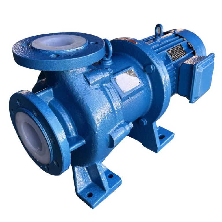
11. Pump/Valve Material and Media Compatibility
Question: Is equipment material resistant to media corrosion?
Common problems:
- Seawater pump uses standard 304 stainless steel (pitting occurs), should use 316L or duplex steel.
- Wastewater pump uses cast iron (rapid corrosion), should use stainless steel or rubber-lined.
- Sulfuric acid piping uses carbon steel (perforation), should use 316L or PTFE-lined.
Check items:
- Based on media pH, chloride content, temperature, solids content, consult corrosion handbook or supplier to confirm material.
Recommendation:
- Critical equipment (main pumps, high temperature/pressure valves) material selection should be reviewed by owner or third-party engineer.
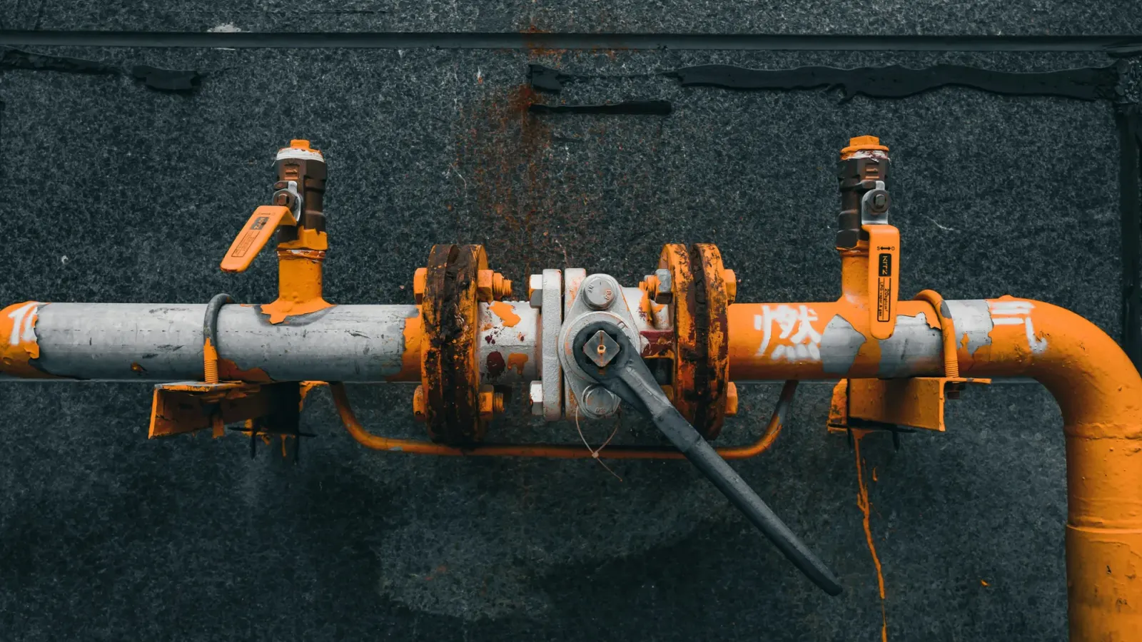
12. Surface Coating and Environmental Suitability
Question: Is equipment coating suitable for site environment (high temperature, humidity, salt spray, UV)?
Check items:
- Outdoor equipment: Require epoxy or polyurethane coating (UV resistant, salt spray resistant), coating thickness ≥ 200μm.
- High-temperature equipment: Require high-temperature coating (e.g., silicone paint), or no coating (e.g., polished stainless steel).
- Coastal projects: Require salt spray test report (e.g., ASTM B117, 1000 hours no corrosion).
Summary: 90% of Interface Problems Can Be Avoided During Procurement
3 Recommendations:
- Attach technical specification to purchase contract: Include all interface requirements (flanges, voltage, signals, materials) in specification as contract appendix. Supplier must strictly comply.
- Hold design coordination meeting before mobilization: Gather pump, valve, piping, electrical, instrumentation, civil leads together to cross-check interfaces item by item.
- Review supplier drawings before fabrication: All equipment GA drawings, foundation drawings, electrical drawings must be submitted to owner or EPC for review and approval before manufacturing starts.
If you are sourcing pumps, valves or related equipment for a project, send KFE your equipment list and operating data and we will help with selection and quotation.
Related industry: Chemical & Pharmaceutical